DNR
Preformances

Technical data
(*) A = 07RN-F 4G1.5+3x1 - 10 m (standard version). Electrical and mechanical features are equal to the cable H07RN-F B = NSSHOU-J
4G1.5+2x0.75 - 10 m (ATEX version)
Preformances

Technical data
(*) A = 07RN-F 4G1.5+3x1 - 10 m (standard version). Electrical and mechanical features are equal to the cable H07RN-F B =
NSSHOU-J 4G1.5+2x0.75 - 10 m (ATEX version)
Preformances

Technical data
(*) A = 07RN-F 4G1.5+3x1 - 10 m (standard version). Electrical and mechanical features are equal to the cable H07RN-F B = NSSHOU-J
4G1.5+2x0.75 - 10 m (ATEX version)
Preformances

Technical data
(*) A = 07RN-F 4G1.5+3x1 - 10 m (standard version). Electrical and mechanical features are equal to the cable H07RN-F
B =
NSSHOU-J 4G1.5+2x0.75 - 10 m (ATEX version)
Preformances

Technical data
(*) A = 07RN-F 4G1.5+3x1 - 10 m (standard version). Electrical and mechanical features are equal to the cable H07RN-F
B =
NSSHOU-J 4G1.5+2x0.75 - 10 m (ATEX version)
Preformances
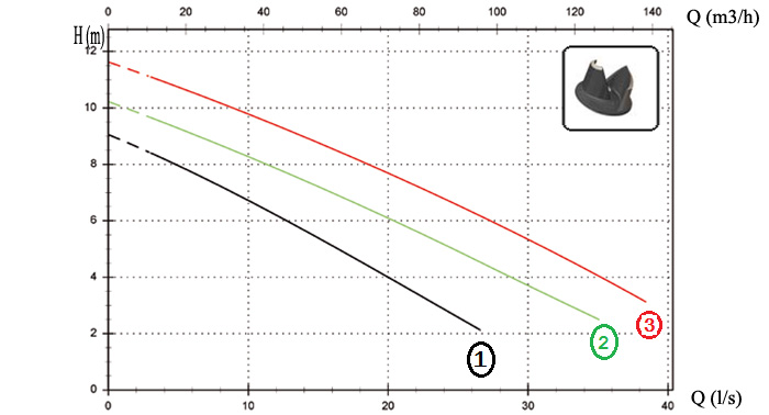

Technical data
(*) A = 07RN-F 4G1.5+3x1 - 10 m (standard version). Electrical and mechanical features are equal to the cable H07RN-F
B =
NSSHOU-J 4G1.5+2x0.75 - 10 m (ATEX version)
Preformances
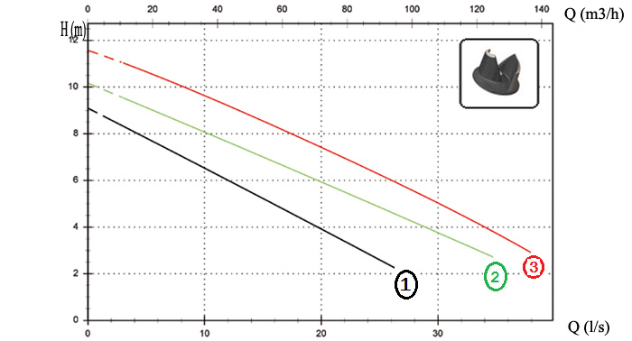

Technical data
(*) A = 07RN-F 4G1.5+3x1 - 10 m (standard version). Electrical and mechanical features are equal to the cable H07RN-F
B =
NSSHOU-J 4G1.5+2x0.75 - 10 m (ATEX version)
Preformances
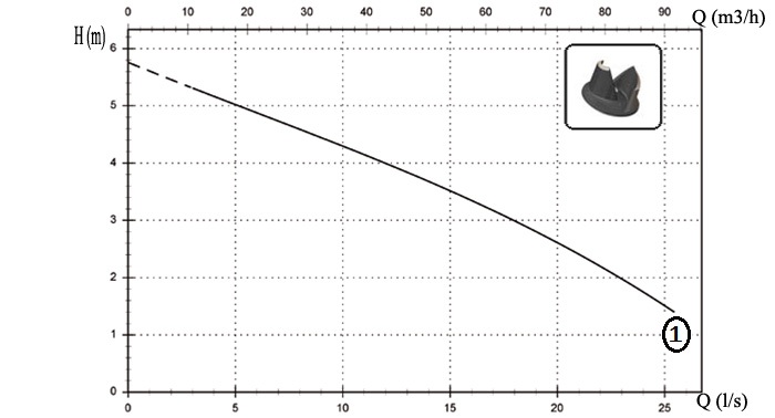

Technical data
(*) A = 07RN-F 4G1.5+3x1 - 10 m (standard version). Electrical and mechanical features are equal to the cable H07RN-F
B =
NSSHOU-J 4G1.5+2x0.75 - 10 m (ATEX version)
Preformances


Technical data
(*) A = 07RN-F 4G1.5+3x1 - 10 m (standard version). Electrical and mechanical features are equal to the cable H07RN-F
B =
NSSHOU-J 4G1.5+2x0.75 - 10 m (ATEX version)
Preformances
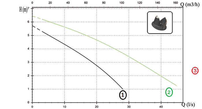

Technical data
(*) A = 07RN-F 4G1.5+3x1 - 10 m (standard version). Electrical and mechanical features are equal to the cable H07RN-F
B =
NSSHOU-J 4G1.5+2x0.75 - 10 m (ATEX version)
Preformances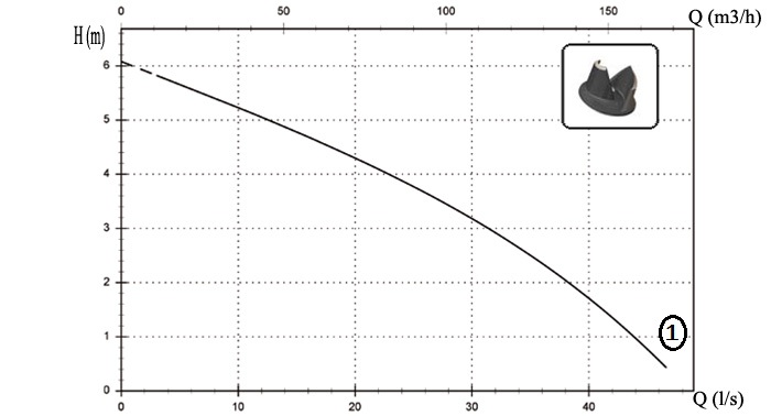

Technical data
(*) A = 07RN-F 4G1.5+3x1 - 10 m (standard version). Electrical and mechanical features are equal to the cable H07RN-F
B =
NSSHOU-J 4G1.5+2x0.75 - 10 m (ATEX version)
DNR
N
A
E
T
T
C
T
C
D
T
C
D
T
T
C
G
T
C
S
T
T
S
T
R
T
R
G
F
T
C
G
F
T
N
CC
2SIC
SICM
SICAL
2SICAL
NOTE: For single phase pumps thermal protections into the winding have to be connected to the electrical panel.Multi-channel open impeller
General characteristics
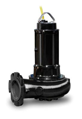
• Multi-channel open impeller
• 1,1 ÷ 4,1 kW motor power
• 2 / 4 / 6 poles
• DN65 ÷ DN150 delivery port
• 40 ÷ 100 mm free passage
• Multi-channel open impeller
• 1,1 ÷ 4,1 kW motor power
• 2 / 4 / 6 poles
• DN65 ÷ DN150 delivery port
• 40 ÷ 100 mm free passage

| Electromechanical assembly | ||||||||||||||
| Electromechanical assembly in GJL-250 cast iron, for submerged operation. Seal set comprising | ||||||||||||||
| 2 (two) opposing silicon carbide mechanical seals in inspectable oil sump. Ecological dry motor. | ||||||||||||||
| Separate pump body. Series available in explosion-proof version | ||||||||||||||
| Applications | ||||||||||||||
| Designed for mainly professional and industrial use such as wastewater treatment plants, | ||||||||||||||
| sewage systems and livestock farms, it is particularly suitable for the treatment of liquids | ||||||||||||||
| containing suspended solids or filaments, and low or medium density activated sludges. The | ||||||||||||||
| pump is also available in explosion-proof version with ATEX certification. This series is prefitted | ||||||||||||||
| for installation of the ZENIT cooling system for dry or semi-submerged installation | ||||||||||||||
| Construction materials | ||||||||||||||
|
| operating limits | ||||||||||||||
|
Cooling by means of
process liquid
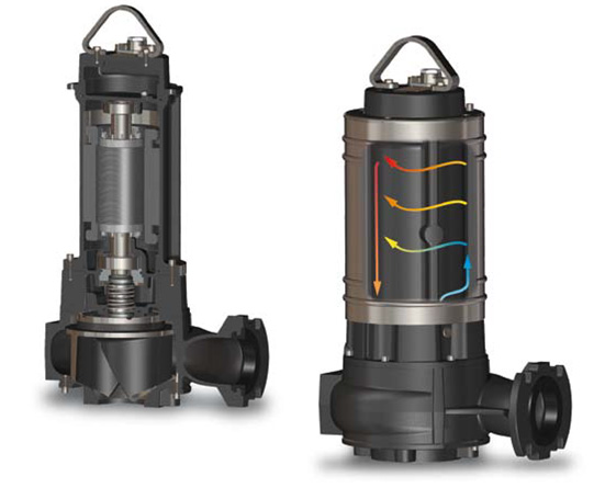
The rear of the impeller is specially shaped to convey some of the process liquid into the cavity between the body and the jacket to cool the motor. Once the cavity is full, the liquid is drawn into the pump body along a special pipe and then expelled.
The rear of the impeller is specially shaped to convey some of the process liquid into the cavity between the body and the jacket to cool the motor. Once the cavity is full, the liquid is drawn into the pump body along a special pipe and then expelled.

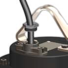 |
Cable gland Cable gland system to guarantee perfect water-tightness. The GAS thread ring-nut can be removed to fix a rigid or flexible duct to the cable gland to protect the power supply cable |
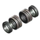 |
Mechanical seals Two mechanical seals in silicon carbide (2SiC) |
|
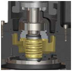 |
Oil sump Large oil sump to guarantee longer mechanical seal lifetime |
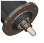 |
Drive shaft Impeller connected to the drive shaft by means of tapered coupling |
|
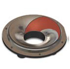 |
Anti-clogging system The special design of the hydraulic part ensures the expulsion of suspended solids and prevents fouling of the impeller |
 |
EX Models available on request with ATEX certification, suitable for installation in the presence of potentially explosive gases, powders and liquids |
|
Models with horizontal DN65 PN10-16 flanged delivery port - 2 poles
Preformances


Technical data
| V | Phases |
P1 (kW) |
P2 (kW) | A | Rpm | Ø | Cable (*) | Free passage | ||||
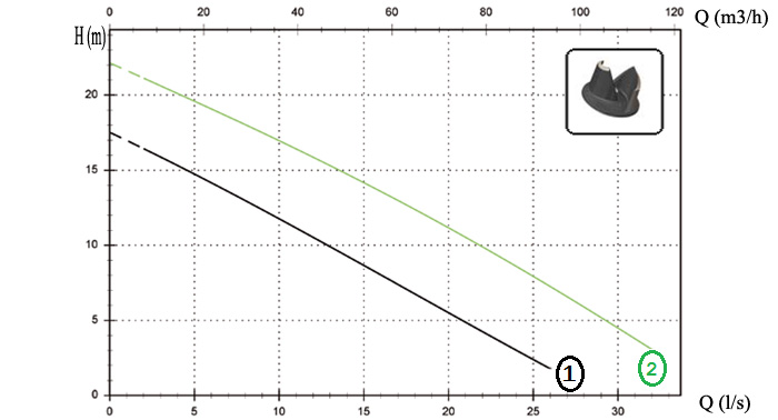
| ① | DRN | 250/2/65 | A1DM/50 | 230 | 1 | 2.8 | 1.8 | 12.5 | 2900 | DN65 PN10-16 | A - B | 40 mm |
| V | Phases |
P1 (kW) |
P2 (kW) | A | Rpm | Ø | Cable (*) | Free passage | ||||
| ① | DRN | 250/2/65 | A1DM/50 | 230 | 1 | 2.5 | 1.8 | 4.3 | 2900 | DN65 PN10-16 | A - B | 40 mm |
| ② | DRN | 300/2/65 | A1DM/50 | 230 | 1 | 2.9 | 2.2 | 5.1 | 2900 | DN65 PN10-16 | A - B | 40 mm |
(*) A = 07RN-F 4G1.5+3x1 - 10 m (standard version). Electrical and mechanical features are equal to the cable H07RN-F B = NSSHOU-J
4G1.5+2x0.75 - 10 m (ATEX version)
Models with horizontal DN65 PN10-16 flanged delivery port - 2 poles
Preformances


Technical data
| V | Phases |
P1 (kW) |
P2 (kW) | A | Rpm | Ø | Cable (*) | Free passage | ||||
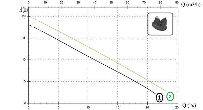
| ① | DRN | 400/2/65 | A1FT/50 | 400 | 3 | 4.0 | 3 | 6.7 | 2900 | DN65 PN10-16 | A - B | 50 mm |
| ② | DRN | 550/2/65 | A1FT/50 | 400 | 3 | 5.0 | 4.1 | 8.1 | 2900 | DN65 PN10-16 | A - B | 50 mm |
(*) A = 07RN-F 4G1.5+3x1 - 10 m (standard version). Electrical and mechanical features are equal to the cable H07RN-F B =
NSSHOU-J 4G1.5+2x0.75 - 10 m (ATEX version)
Models with horizontal DN65 PN10-16 flanged delivery port - 2 poles
Preformances


Technical data
| V | Phases |
P1 (kW) |
P2 (kW) | A | Rpm | Ø | Cable (*) | Free passage | ||||
| ① | DRN | 250/2/65 | A1DM/50 | 230 | 1 | 2.8 | 1.8 | 12.5 | 2900 | DN65 PN10-16 | A - B | 40 mm |
| V | Phases |
P1 (kW) |
P2 (kW) | A | Rpm | Ø | Cable (*) | Free passage | ||||
| ① | DRN | 250/2/65 | A1DM/50 | 230 | 1 | 2.5 | 1.8 | 4.3 | 2900 | DN65 PN10-16 | A - B | 40 mm |
| ② | DRN | 300/2/65 | A1DM/50 | 230 | 1 | 2.9 | 2.2 | 5.1 | 2900 | DN65 PN10-16 | A - B | 40 mm |
(*) A = 07RN-F 4G1.5+3x1 - 10 m (standard version). Electrical and mechanical features are equal to the cable H07RN-F B = NSSHOU-J
4G1.5+2x0.75 - 10 m (ATEX version)
Models with horizontal DN80 PN10-16 flanged delivery port - 2 poles
Preformances


Technical data
| V | Phases |
P1 (kW) |
P2 (kW) | A | Rpm | Ø | Cable (*) | Free passage | ||||
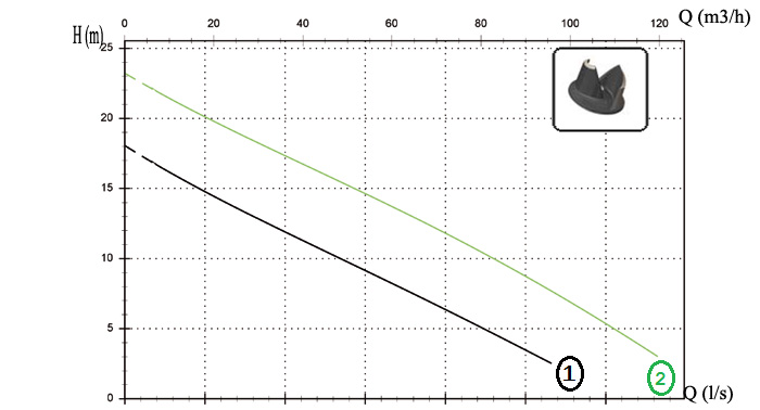
| ① | DRN | 400/2/100 | A1FT/50 | 400 | 3 | 4.0 | 3 | 6.7 | 2900 | DN100 PN10-16 | A - B | 50 mm |
| ② | DRN | 550/2/100 | A1FT/50 | 400 | 3 | 5.0 | 4.1 | 8.7 | 2900 | DN100 PN10-16 | A - B | 50 mm |
NSSHOU-J 4G1.5+2x0.75 - 10 m (ATEX version)
Models with horizontal DN100 PN10-16 flanged delivery port - 2 poles
Preformances


Technical data
| V | Phases |
P1 (kW) |
P2 (kW) | A | Rpm | Ø | Cable (*) | Free passage | ||||
| ① | DRN | 400/2/100 | A1FT/50 | 400 | 3 | 4.0 | 3 | 6.7 | 2900 | DN100 PN10-16 | A - B | 50 mm |
| ② | DRN | 550/2/100 | A1FT/50 | 400 | 3 | 5.0 | 4.1 | 8.7 | 2900 | DN100 PN10-16 | A - B | 50 mm |
NSSHOU-J 4G1.5+2x0.75 - 10 m (ATEX version)
Models with horizontal DN80 PN10-16 flanged delivery port - 4 poles
Preformances


Technical data
| V | Phases |
P1 (kW) |
P2 (kW) | A | Rpm | Ø | Cable (*) | Free passage | ||||
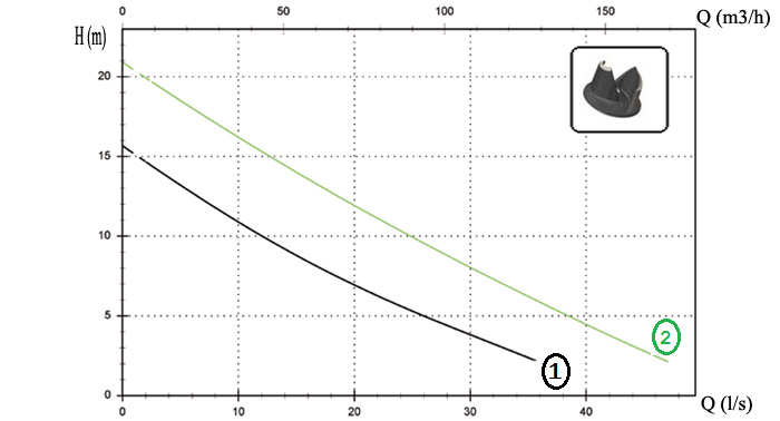
| ① | DRN | 400/2/100 | A1FT/50 | 400 | 3 | 2.0 | 1.5 | 4.1 | 1450 | DN80 PN10-16 | A - B | 80 mm |
| ② | DRN | 550/2/100 | A1FT/50 | 400 | 3 | 2.9 | 2.2 | 5.8 | 1450 | DN80 PN10-16 | A - B | 80 mm |
| ③ | DRN | 550/2/100 | A1FT/50 | 400 | 3 | 3.7 | 3 | 7.3 | 1450 | DN80 PN10-16 | A - B | 80 mm |
NSSHOU-J 4G1.5+2x0.75 - 10 m (ATEX version)
Models with horizontal DN100 PN10-16 flanged delivery port - 4 poles
Preformances


Technical data
| V | Phases |
P1 (kW) |
P2 (kW) | A | Rpm | Ø | Cable (*) | Free passage | ||||
| ① | DRN | 400/2/100 | A1FT/50 | 400 | 3 | 2.0 | 1.5 | 4.1 | 1450 | DN100 PN10-16 | A - B | 80 mm |
| ② | DRN | 400/2/100 | A1FT/50 | 400 | 3 | 2.9 | 2.2 | 5.8 | 1450 | DN100 PN10-16 | A - B | 80 mm |
| ③ | DRN | 400/2/100 | A1FT/50 | 400 | 3 | 3.7 | 3 | 7.3 | 1450 | DN100 PN10-16 | A - B | 80 mm |
NSSHOU-J 4G1.5+2x0.75 - 10 m (ATEX version)
Models with horizontal DN80 PN10-16 flanged delivery port - 6 poles
Preformances


Technical data
| V | Phases |
P1 (kW) |
P2 (kW) | A | Rpm | Ø | Cable (*) | Free passage | ||||
| ① | DRN | 150/6/80 | A1FT/50 | 400 | 3 | 1.6 | 1.1 | 3.7 | 960 | DN80 PN10-16 | A - B | 80 mm |
NSSHOU-J 4G1.5+2x0.75 - 10 m (ATEX version)
Models with horizontal DN100 PN10-16 flanged delivery port - 4 poles
Preformances


Technical data
| V | Phases |
P1 (kW) |
P2 (kW) | A | Rpm | Ø | Cable (*) | Free passage | ||||
| ① | DRN | 400/2/100 | A1FT/50 | 400 | 3 | 2.0 | 1.5 | 4.1 | 1450 | DN100 PN10-16 | A - B | 80 mm |
| ② | DRN | 400/2/100 | A1FT/50 | 400 | 3 | 2.9 | 2.2 | 5.8 | 1450 | DN100 PN10-16 | A - B | 80 mm |
| ③ | DRN | 400/2/100 | A1FT/50 | 400 | 3 | 3.7 | 3 | 7.3 | 1450 | DN100 PN10-16 | A - B | 80 mm |
NSSHOU-J 4G1.5+2x0.75 - 10 m (ATEX version)
Models with horizontal DN100 PN10-16 flanged delivery port - 6 poles
Preformances


Technical data
| V | Phases |
P1 (kW) |
P2 (kW) | A | Rpm | Ø | Cable (*) | Free passage | ||||
| ① | DRN | 150/6/100 | A1FT/50 | 400 | 3 | 1.6 | 1.1 | 3.7 | 960 | DN100 PN10-16 | A - B | 80 mm |
| ② | DRN | 250/6/100 | A1FT/50 | 400 | 3 | 2.6 | 1.8 | 5.7 | 960 | DN100 PN10-16 | A - B | 100 mm |
NSSHOU-J 4G1.5+2x0.75 - 10 m (ATEX version)
Models with horizontal DN150 PN10-16 flanged delivery port - 6 poles
Preformances


Technical data
| V | Phases |
P1 (kW) |
P2 (kW) | A | Rpm | Ø | Cable (*) | Free passage | ||||
| ① | DRN | 250/6/150 | A1FT/50 | 400 | 3 | 2.6 | 1.8 | 5.7 | 960 | DN150 PN10-16 | A - B | 100 mm |
NSSHOU-J 4G1.5+2x0.75 - 10 m (ATEX version)
DNR
Versions available
Electrical variants
Cooling
Mechanical Seals
N
A
E
T
T
C
T
C
D
T
C
D
T
T
C
D
G
T
C
D
G
T
T
C
G
T
C
S
T
T
C
S
G
T
C
S
G
T
T
S
T
R
T
R
G
F
T
C
G
F
T
N
CC
2SIC
SICM
SICAL
2SICAL
DRN 250/2/65 A1DM/50
DRN 250/2/65 A1DT/50
DRN 300/2/65 A1DT/50
DRN 400/2/65 A1FT/50
DRN 550/2/65 A1FT/50
*
*
*
*
*
*
*
*
*
*
*
*
*
*
*
*
*
*
*
*
*
*
*
*
*
DRN 250/2/80 A1DM/50
DRN 250/2/80 A1DT/50
DRN 300/2/80 A1DT/50
DRN 400/2/80 A1FT/50
DRN 550/2/80 A1FT/50
*
*
*
*
*
*
*
*
*
*
*
*
*
*
*
*
*
*
*
*
*
*
*
*
*
DRN 400/2/100 A1FT/50
DRN 550/2/100 A1FT/50
*
*
*
*
*
*
*
*
*
*
DRN 200/4/80 A1DT/50
DRN 300/4/80 A1FT/50
DRN 400/4/80 A1FT/50
*
*
*
*
*
*
*
*
*
*
*
*
*
*
*
DRN 200/4/100 A1DT/50
DRN 300/4/100 A1FT/50
DRN 400/4/100 A1FT/50
*
*
*
*
*
*
*
*
*
*
*
*
*
*
*
DRN 150/6/80 A1DT/50
*
*
*
*
*
DRN 150/6/100 A1DT/50
DRN 250/6/100 A1FT/50
*
*
*
*
*
*
*
*
*
*
DRN 250/6/150 A1FT/50
*
*
*
*
*
Start capacitor inside the pump. Circuit breaker supplied but not connected to the pump cable.
The use of an electrical panel as circuit breaker housing is mandatory. For installation please see use and maintenance instructions
booklet. The version complete with probe is not available with ATEX certificate.
Packaging dimension
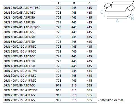
Overall dimensions and weights

